Hi Jad,
Very interesting. I would love to see avideo. It seems to me you should have enough Axis Channels. 5 real Axes + 2 dummy Axes = 7 axis.
However a better way might be to use Kinematics or the GeoCorrection Table. I think that transformation is equivalent to a 45 degree rotation.
Although I just tried it and I see some problems. Give me some time and I will try to come up with a solution.
Regards
TK
| Group: DynoMotion |
Message: 5532 |
From: Tom Kerekes |
Date: 8/13/2012 |
| Subject: Re: coordinate transformation |
Hi Jad,
Here is an experimental version that should allow the Geo Correction Table to do your required transformation.
There were several bugs and issues with the Geo Correction method that should now be fixed.
This version also includes an example Geo Correction Table file that should do the Transformation you require. It will be installed as:
C:\KMotion430c\KMotion\Data\MeasurementsPlusMinus.txt
Select it in KMotionCNC | Tool Setup | Tool Setup Files | Geo File
There is a description here:
Please let me know if it works for you.
Regards
TK
| Group: DynoMotion |
Message: 5545 |
From: jadrizk89 |
Date: 8/15/2012 |
| Subject: Re: coordinate transformation |
Dear Tom,
I can see the new version of the kmotioncnc is improved, especially with the added block delete button which comes in very useful. If possible to add a symbol other than '/' to skip more than one block. So if i want to skip a 100 lines perhaps i don't have to place a '/' before each line.
As for my previous question, I would like to clarify my actual coordinate transformation.
The geo transformation method you proposed is very effective and gives a linear interpolation on a 4000*4000 grid array which if used, is as correct as the actual transformation needed even if it wasn't linear.
The actual transformation I would like to do in my machine is on the 4th and 5th axis which are rotary axes on my machine and the software only has the geo file for the X,Y,Z coordinates.
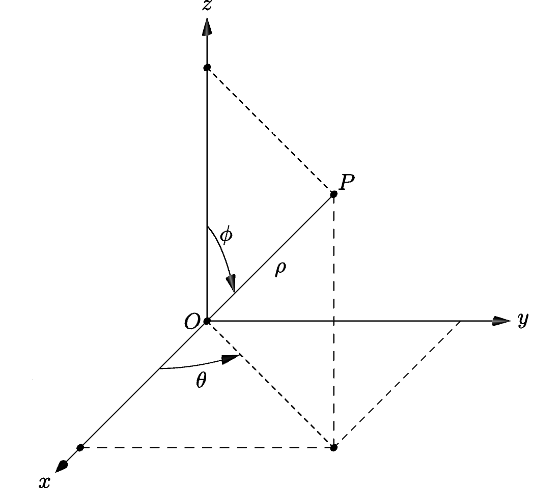
I have a cam software which will give me aside from XYZ, A and B coordinates which are the phi and theta angles from the cylindrical coordinate system. After building my machine, I found the transformation functions that will transform the A and B coordinates to motor 6 and motor 7 rotations. In my program, ch6 and ch7 control the 2 motors in question without being in the coordinate system. ch4 and ch5 don't control any motors, they have no input and no output, they are just used to get A and B from the coordinate system.
In my C program right now I have: ( I haven't copied the whole program)
DefineCoordSystem6(0,1,3,4,5,-1); ( ch4 and ch5 are A and B from G code)
double o1,o2,phi,theta,last_o1;
theta=ch4->Dest;
phi=ch5->Dest;
o2=acos(4*cos(phi*PI/180)-3);
ch7->Dest=o2*1000000/(360);
o1=theta+90-atan(sqrt(3)/2*(1-cos(o2))/sin(o2))*180/PI;
ch6->Dest=o1*1000000/(360);
I really hope my mail was useful. Any help from you will be appreciated. Thanks in advance.
Sincerely,
Jad
--- In DynoMotion@yahoogroups.com, Tom Kerekes <tk@...> wrote:
>
> Hi Jad,
> Â
> Here is an experimental version that should allow the Geo Correction Table to do your required transformation.
> Â
> http://dynomotion.com/Software/KMotion430c.exe
> Â
> There were several bugs and issues with the Geo Correction method that should now be fixed.
> Â
> This version also includes an example Geo Correction Table file that should do the Transformation you require. It will be installed as:
> Â
> C:\KMotion430c\KMotion\Data\MeasurementsPlusMinus.txt
> Â
> Select it in KMotionCNC | Tool Setup | Tool Setup Files | Geo File
> Â
> There is a description here:
> Â
> http://dynomotion.com/Help/KMotionCNC/GeoCorrection.htm
> Â
> Please let me know if it works for you.
> Â
> Regards
> TKÂ
> Â
>
> From: Tom Kerekes <tk@...>
> To: "DynoMotion@yahoogroups.com" <DynoMotion@yahoogroups.com>
> Sent: Friday, August 10, 2012 1:43 PM
> Subject: Re: [DynoMotion] Re: coordinate transformation
>
>
> Hi Jad,
> Â
> Very interesting. I would love to see avideo. It seems to me you should have enough Axis Channels. 5 real Axes + 2 dummy Axes = 7 axis.
> Â
> However a better way might be to use Kinematics or the GeoCorrection Table. I think that transformation is equivalent to a 45 degree rotation.
> Â
> Although I just tried it and I see some problems. Give me some time and I will try to come up with a solution.
> Â
> Regards
> TK
> Â
> Â
>
> From: Jad Rizk <jadrizk89@...>
> To: DynoMotion@yahoogroups.com
> Sent: Thursday, August 9, 2012 10:53 PM
> Subject: [DynoMotion] Re: coordinate transformation
>
>
> Â
>
>
> hello,
> >
> >
> >I am building a 5 axis machine and using the kflop-kanalog board to control it. I am using servo motors and controling the with +/- 10V.
> >
> >
> >I have a two motors that need two coordinates from the G code to control it.
> >As an example: G0 X30 Y20 Â then i want the first motor to move X+Y, and the second motor X-Y so i want the first one to move 50 and the second one 10.
>
> right now i put X and Y axis as virtual axes ( no output, no input) and the two motors on ch2 and ch3.
> so i have in the init file:
>
>  ch2=>dest  =  ch0=>dest  +  ch1=>destÂ
>  ch3=>dest  =  ch0=>dest  -  ch1=>dest
>
>
>  I have already tested the program and it works just fine.
> The problem is that i am loosing two axes in the board (ch0, ch1).
> I was wondering if this can be done using only two channels on the board. If I can input X and Y from the Gcode on ch0 and ch1 then  getÂ
> ch0 dest= x+y
> ch1 dest= x-y
> without having to configure two extra axes with no output and no input.
>
> Thank you in advance for your help
> |
|
| Group: DynoMotion |
Message: 5547 |
From: Tom Kerekes |
Date: 8/16/2012 |
| Subject: Re: coordinate transformation |
Hi Jad,
It would be helpful to know the mechanics of your system. Also you didn't answer my question on whether your current method works and why you need the other 2 axes.
But to do this it would be necessary to create a Kinematics Class. Do you have Visual Studio 2008 Standard to be able to compile the PC libraries and make changes?
Take a look at the Kinematics3Rod.cpp example. What would be an appropriate name for this type of AB transformation?
We could make a new Kinematics Class and modify the TransformCADtoActuators with your equations.
Regards
TK
| Group: DynoMotion |
Message: 5560 |
From: Jad Rizk |
Date: 8/16/2012 |
| Subject: Re: coordinate transformation |
Hello Tom,
I have already tested my current method and it works. I am currently using all 8 channels, X, two Y channels (one is in slave mode), Z , two virtual channels for A and B coordinates and the last two for the pitch yaw motors I have on the machine. So for now everything is working. I just wanted to see If there was a better way to implement my kinematics transformation.
I checked the kinematics3rod example briefly and as you said we could create a new kinematics class with my equations similar to the one in the example.
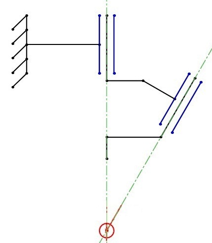
I am using the configuration shown in the figure attached. From that configuration I was able to get my equations. so the transformation is actually spherical coordinates (given by the cam software) to the motor rotation wanted.
Right now i don't have visual studio 2008, I opened the file using notepad. I will try to get it soon and then try to write my transformation into the program.
If you want me to send you any other pictures let me know.
I will keep you updated with my project and talk to you again when I get the visual studio and start trying to write the program, but i will need help since I don't have much experience in programming.
Thank you, Jad On Thu, Aug 16, 2012 at 8:58 PM, Tom Kerekes <tk@...> wrote:
Hi Jad,
It would be helpful to know the mechanics of your system. Also you didn't answer my question on whether your current method works and why you need the other 2 axes.
But to do this it would be necessary to create a Kinematics Class. Do you have Visual Studio 2008 Standard to be able to compile the PC libraries and make changes?
Take a look at the Kinematics3Rod.cpp example. What would be an appropriate name for this type of AB transformation?
We could make a new Kinematics Class and modify the TransformCADtoActuators with your equations.
Regards
TK
| Group: DynoMotion |
Message: 5561 |
From: Jad Rizk |
Date: 8/16/2012 |
| Subject: Re: coordinate transformation [2 Attachments] |
This is a prototype build to test the motors, the controller and the system. Please let me know What you think. On Fri, Aug 17, 2012 at 8:28 AM, Jad Rizk <jadrizk89@...> wrote:
[Attachment(s) from Jad Rizk included below]
Hello Tom,
I have already tested my current method and it works. I am currently using all 8 channels, X, two Y channels (one is in slave mode), Z , two virtual channels for A and B coordinates and the last two for the pitch yaw motors I have on the machine. So for now everything is working. I just wanted to see If there was a better way to implement my kinematics transformation.
I checked the kinematics3rod example briefly and as you said we could create a new kinematics class with my equations similar to the one in the example.
I am using the configuration shown in the figure attached. From that configuration I was able to get my equations. so the transformation is actually spherical coordinates (given by the cam software) to the motor rotation wanted.
Right now i don't have visual studio 2008, I opened the file using notepad. I will try to get it soon and then try to write my transformation into the program.
If you want me to send you any other pictures let me know.
I will keep you updated with my project and talk to you again when I get the visual studio and start trying to write the program, but i will need help since I don't have much experience in programming.
Thank you, Jad On Thu, Aug 16, 2012 at 8:58 PM, Tom Kerekes <tk@...> wrote:
Hi Jad,
It would be helpful to know the mechanics of your system. Also you didn't answer my question on whether your current method works and why you need the other 2 axes.
But to do this it would be necessary to create a Kinematics Class. Do you have Visual Studio 2008 Standard to be able to compile the PC libraries and make changes?
Take a look at the Kinematics3Rod.cpp example. What would be an appropriate name for this type of AB transformation?
We could make a new Kinematics Class and modify the TransformCADtoActuators with your equations.
Regards
TK
| Group: DynoMotion |
Message: 5563 |
From: Tom Kerekes |
Date: 8/17/2012 |
| Subject: Re: coordinate transformation [1 Attachment] |
Wow Jad, beautiful I love it.
The video really helps. I think it is great from a simplicity and work envelope stand point. Maybe not so much from a mechanical stiffness stand point.
Is there a name for this type of arrangement?
While you are waiting to obtain MS VS Standard if you make the changes I could check over the code and compile it for you. But I suspect it may take some iterations to get all the directions and parameters correct so it would be best if you could debug and make changes yourself (Eventually we hope to eliminate this dependency on MS Visual Studio for the KMotion core libraries but we aren't there
yet).
Regards TK
From: Jad Rizk <jadrizk89@...>
To: DynoMotion@yahoogroups.com
Sent: Thursday, August 16, 2012 10:53 PM
Subject: Re: [DynoMotion] Re: coordinate transformation [1 Attachment]
This is a prototype build to test the motors, the controller and the system. Please let me know What you think. On Fri, Aug 17, 2012 at 8:28 AM, Jad Rizk <jadrizk89@...> wrote:
[Attachment(s) from Jad Rizk included below]
Hello Tom,
I have already tested my current method and it works. I am currently using all 8 channels, X, two Y channels (one is in slave mode), Z , two virtual channels for A and B coordinates and the last two for the pitch yaw motors I have on the machine. So for now everything is working. I just wanted to see If there was a better way to implement my kinematics transformation.
I checked the kinematics3rod example briefly and as you said we could create a new kinematics class with my equations similar to the one in the example.
I am using the configuration shown in the figure attached. From that configuration I was able to get my equations. so the transformation is actually spherical coordinates (given by the cam software) to the motor rotation wanted.
Right now i don't have visual studio 2008, I opened the file using notepad. I will try to get it soon and then try to write my transformation into the program.
If you want me to send you any other pictures let me know.
I will keep you updated with my project and talk to you again when I get the visual studio and start trying to write the program, but i will need help since I don't have much experience in programming.
Thank you, Jad On Thu, Aug 16, 2012 at 8:58 PM, Tom Kerekes <tk@...> wrote:
Hi Jad,
It would be helpful to know the mechanics of your system. Also you didn't answer my question on whether your current method works and why you need the other 2 axes.
But to do this it would be necessary to create a Kinematics Class. Do you have Visual Studio 2008 Standard to be able to compile the PC libraries and make changes?
Take a look at the Kinematics3Rod.cpp example. What would be an appropriate name for this type of AB transformation?
We could make a new Kinematics Class and modify the TransformCADtoActuators with your equations.
Regards
TK
| | | | | | | | | | | |